M.2-IIRO-4

ACCES I/O M.2-IIRO-4 4 Digital Inputs and 4 Relay Outputs with COS M.2 Card
M.2-IIRO-4
- 2260/2280 sized M.2 Card with B & M keys and latching I/O connectors
- 4 optically-isolated non-polarized inputs
- 4 electromechanical 1A relay outputs
- Change-of-State (COS) detection IRQ generation
- 9” cable (228MM), standard
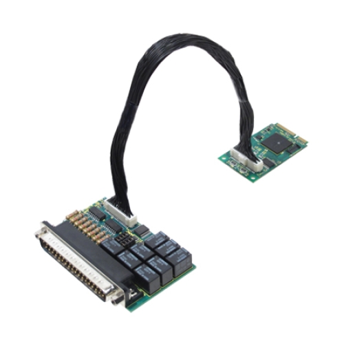
- Panel-mountable isolation module with 37-pin male D-Sub connector
- RoHS standard
Details
The ACCES I/O M.2-IIRO-4 consists of a 2260/2280 sized M.2 interface card that connects to a Mobile-ITX-sized, DB-37M Isolation Module via an included 9” cable. That module is designed to be easily panel-mounted in any application environment. It uses the high speed PCI Express bus to transfer digital data to and from the card. The digital I/O is compatible with 8255 PPI chips making it easy to program. This allows for simple and trouble-free migration from other ACCES PCI and PCI Express digital I/O cards, but also provides for advanced features enabled by the onboard FPGA logic.
The M.2-IIRO cards are well suited to complex environments, mitigating otherwise challenging ground-loops, high-common-mode, and transient voltage spikes common in electrically-noisy industrial or factory locations. The broad voltage compatibility and high current outputs allows use in a wide range of applications.
The non-polarized inputs support both AC and DC, and configuration jumpers allow 4.7ms input filters to be enabled per-channel, as desired – required for AC use. The isolated inputs support voltages from 3 to 31 VDC/VAC RMS [40Hz to 10000Hz], as well as standard 12/24 AC control transformer signals.
Outputs are 5 Form C (“Single-pole, double-throw”, or SPDT) and 3 Form A (SPST) electromechanical relays capable of 1A continuous-current load.
Change of State (COS) detection and interrupt capabilities are designed to relieve software from polling routines that can consume valuable processing time. Each port can be programmed for detecting state changes on their lines, in which any changes of the enabled port's bits (low-to-high or high-to-low) will generate an IRQ. An ISR (interrupt service routine) then determines which bit changed state and clears the interrupt.
Ordering Info
| M.2-IIRO-8 | 8 Digital Input and 8 Relay Outputs |
| M.2-RO-8 | 8 Relay Outputs |
| M.2-IIRO-4 | 4 Digital Inputs and 4 Relay Outputs |
Downloads
Assured Systems Datasheet (PDF)
A PDF edition of this page with supporting manufacturer datasheets
System Integration
Please ask about how we can configure your solution
Global Operations
We deliver and support products via offices globally
Full Warranty
Industry leading warranties on all solutions as standard
Technical Support
Experienced engineers are on hand to support your project
Can't Find What You Want?
Specification
| PC Interface | M.2 Card |
| Isolated Inputs | 4 |
| Type | Non-polarized, optically isolated from each other and from the computer (CMOS compatible) |
| Voltage | 3 to 31 DC or AC RMS (40 to 10000Hz) |
| Isolation | 500V channel-to-ground and channel-to-channel |
| Resistance | 1.8KΩ in series with opto-coupler |
| Filter Response | Rise-time: 4.7 msFall-time: 4.7 ms |
| Non-Filter Response | Rise-time: 10 μsFall-time: 30 μs |
| Relay Outputs | 4 |
| Type | 5 Form C (SPDT) and 3 Form A (SPST), Ag with Au clad,single crossbar for M.2-IIRO-8; 4 Form C for M.2-IIRO-4 |
| AC Load | 0.5A at 125 VAC (62.5 VA max) |
| DC Load | 1A at 24 VDC (30W max) |
| Switching Voltage | 125 VAC, 60 VDC, max |
| Switching Current | 1A max |
| Contact Resistance | 100 mΩ, max |
| Contact Life | 5 million operations, min |
| Temperature | Operating: 0°C to 70°C (order -T option for industrial temperature -40°C to 85°C)Storage: -65°C to 150°C |
| Humidity | 5% to 95%, non-condensing |
| Power Required | +3.3VDC @ 730ma (typical) all relays on |
Delivery Information
Orders dispatched from Assured Systems USA will be delivered using FedEx.
Payment Methods & Options
Accepted payment methods for US customers include bank transfer, VISA or Mastercard in USD.
ACCES I/O: Warranty and Service Information
All ACCES I/O products distributed in the EMEA come with a 2 year warranty as standard, with additional extension options available upon request. As an official ACCES I/O partner, we are proud to provide customers with peace of mind and the highest quality products, including any systems which have been configured to meet individual specifications.
Related Products
You may also like...